
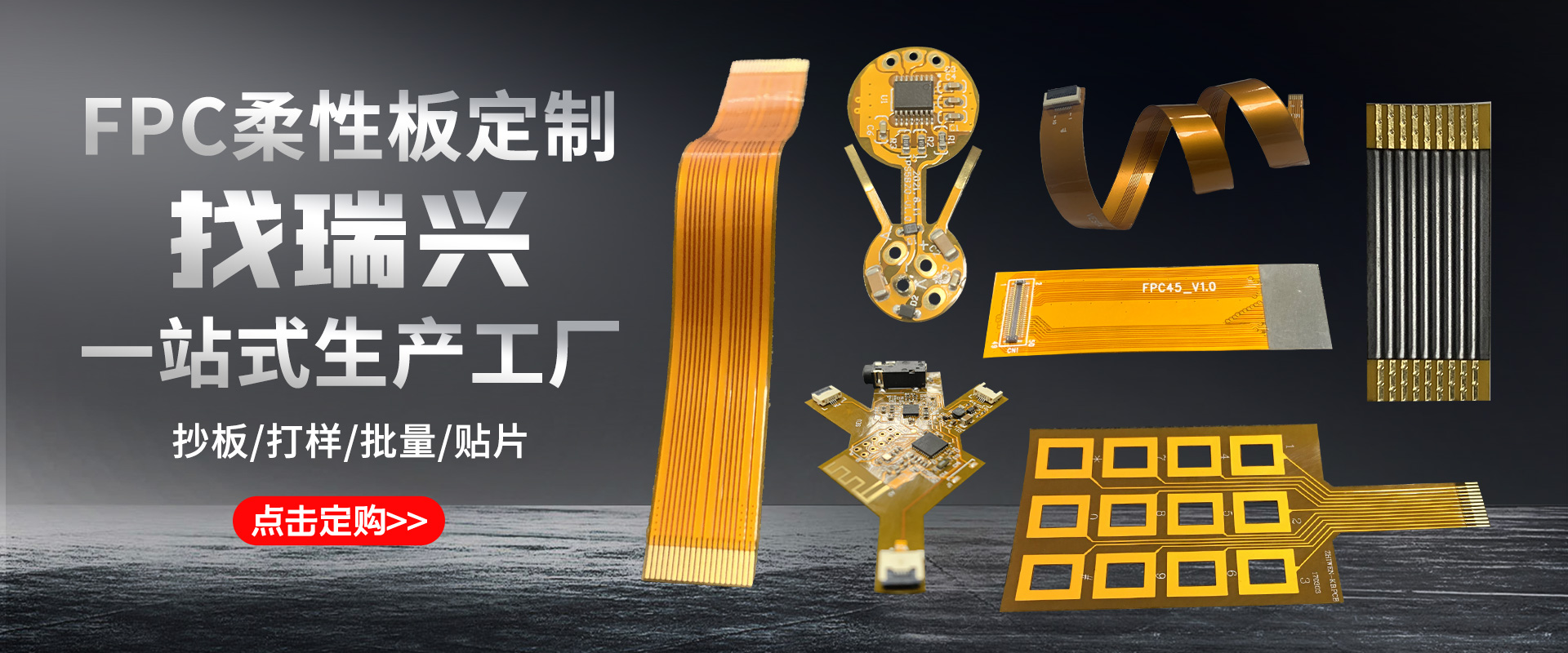
Ruixing fast production of FPC (flexible printed circuit board) SET more detailed interpretation of the process
FPC is also called flexible circuit board. The PCBA assembly welding process of FPC is very different from the assembly of rigid circuit board. Because the hardness of FPC board is not enough, it is soft. If you don't use special carrier board, you can't fix and transmit it. Basic SMT processes such as printing, placement, and furnace cannot be completed.
SMT electronics factory produces FPC (flexible circuit board) process super detailed explanation
one. FPC pretreatment
The FPC board is soft, and is generally not vacuum-packed at the factory. It is easy to absorb the moisture in the air during transportation and storage. It needs to be pre-baked before the SMT is cast, and the water is slowly and forcibly discharged. Otherwise, under the high temperature impact of reflow soldering, the moisture absorbed by the FPC rapidly vaporizes into water vapor to protrude the FPC, which is liable to cause defects such as stratification and foaming of the FPC.
The pre-baking conditions are generally 4-8 hours at a temperature of 80-100 ° C. In special cases, the temperature can be raised to above 125 ° C, but the baking time should be shortened accordingly. Before baking, be sure to test the sample first to determine if the FPC can withstand the set baking temperature. Consult the FPC manufacturer for the appropriate baking conditions. When baking, the FPC stacking should not be too much. 10-20PNL is suitable. Some FPC manufacturers will put a piece of paper between each PNL for isolation. It is necessary to confirm whether the paper for isolation can withstand the set baking. Temperature, if it is not necessary to remove the separator, then bake. The FPC after baking should have no obvious discoloration, deformation, lifting and other defects, and it is necessary to pass the IPQC sampling test before the line can be cast.
two. Production of special carrier
According to the CAD file of the circuit board, read the hole positioning data of the FPC to manufacture a high-precision FPC positioning template and a special carrier plate, so that the diameter of the positioning pin on the positioning template and the positioning hole on the carrier plate and the aperture of the positioning hole on the FPC are match. Many FPCs are not the same thickness because they want to protect some lines or design reasons. Some places are thick and some areas are thin, and some have strengthened metal plates. Therefore, the combination of the carrier board and the FPC needs to be pressed. The actual situation is processed and polished to ensure that the FPC is flat during printing and placement. The material of the carrier board is required to be light and thin, high in strength, low in heat absorption, fast in heat dissipation, and small in warpage after repeated thermal shock. Commonly used carrier materials are synthetic stone, aluminum plate, silica gel plate, special high temperature resistant magnetized steel plate and so on.
three. production process
Here we use the ordinary carrier board as an example to detail the SMT points of the FPC. When using the silica gel plate or the magnetic fixture, the fixing of the FPC is much more convenient, no need to use the tape, and the process points of the printing, patching, welding and other processes are the same.
FPC fixing
Before performing SMT, it is first necessary to accurately fix the FPC on the carrier board. It is important to note that the shorter the storage time between printing, placement and soldering, after the FPC is attached to the carrier, the better. The carrier plate has two types of positioning pins and no positioning pins. The carrier board without the positioning pin should be used together with the positioning template with the positioning pin. First, the carrier board is placed on the positioning pin of the template, so that the positioning pin is exposed through the positioning hole on the carrier board, and the FPC is placed one by one. The exposed locating pins are then taped and the carrier is separated from the FPC positioning template for printing, placement and soldering. A number of spring positioning pins with a length of about 1.5 mm have been fixed on the carrier plate with the positioning pins. The FPC can be directly placed on the spring positioning pins of the carrier plate and then fixed with tape. In the printing process, the spring positioning pin can be completely pressed into the carrier by the steel mesh without affecting the printing effect.
Method 1 (single-sided tape fixing): Fix the four sides of the FPC on the carrier board with a thin high-temperature single-sided tape. Do not allow the FPC to have offset and warp. The viscosity of the tape should be moderate. It must be easily peeled off after reflow and in FPC. There is no residual glue on it. If you use the automatic tape machine, you can quickly cut the length of the tape, which can significantly improve efficiency, save costs and avoid waste.
Method 2 (double-sided tape fixing): firstly attach the high-temperature double-sided tape to the carrier board, the effect is the same as that of the silica gel board, then paste the FPC into the carrier board, pay special attention to the viscosity of the tape should not be too high, otherwise it will peel off after reflow soldering. When it is easy to cause FPC tearing. After repeatedly passing the furnace, the viscosity of the double-sided tape will gradually become lower, and the viscosity is so low that it cannot be reliably fixed when the FPC is fixed. This station is a key station to prevent the FPC from being dirty, and it is necessary to wear a finger sleeve. Before the carrier board is reused, it needs to be properly cleaned. It can be scrubbed with a non-woven cloth cleaning agent or an anti-static dust roller to remove foreign matter such as surface dust and tin beads. Do not use too much force when handling FPC. FPC is fragile and prone to creases and breaks.
FPC solder paste printing
FPC does not have any special requirements for the composition of the solder paste. The size and metal content of the solder ball are based on the fine pitch IC on the FPC, but the FPC has high printing performance requirements for the solder paste, and the solder paste should have excellent properties. Thixotropy, solder paste should be able to print off the mold easily and firmly adhere to the surface of the FPC, without the problem of poor mold release, blocking the leakage of the steel mesh or causing collapse after printing.
Because the FPC is loaded on the carrier, the FPC has a high temperature resistant tape for positioning, so that the plane is inconsistent, so the printed surface of the FPC cannot be as flat as the PCB and the thickness is the same. Therefore, it is not suitable to use a metal scraper, but the hardness should be 80. -90 degree polyurethane type scraper. The solder paste printing machine preferably has an optical positioning system, otherwise it will have a great influence on the printing quality. Although the FPC is fixed on the carrier board, there will always be some slight gap between the FPC and the carrier board, which is hard with the PCB. The biggest difference between the boards, so the setting of the device parameters will have a greater impact on the printing effect.
The printing station is also a key station to prevent the FPC from being dirty. It is necessary to wear a finger sleeve. At the same time, it is necessary to keep the station clean and clean the steel mesh to prevent the solder paste from contaminating the FPC's gold finger and gold-plated buttons.
SMT electronics factory produces FPC (flexible circuit board) process super detailed explanation
FPC patch
According to the characteristics of the product, the number of components and the efficiency of the placement, it can be mounted by medium and high speed placement machines. Since each piece of FPC has an optical MARK mark for positioning, there is little difference between SMD placement on the FPC and placement on the PCB. It should be noted that although the FPC is fixed on the carrier board, the surface may not be as flat as the PCB hard board. There must be a partial gap between the FPC and the carrier board. Therefore, the nozzle drop height, the blowing pressure, etc. Need to be accurately set, the nozzle movement speed needs to be reduced. At the same time, FPC is mostly in the board, and the yield of FPC is relatively low. Therefore, it is normal for the whole PNL to contain some bad PCS. This requires the placement machine to have the BAD MARK identification function. Otherwise, in the production of such non-standard In the case that PNL is a good board, the production efficiency will be greatly reduced.
FPC reflow soldering
A forced hot convection infrared reflow oven should be used so that the temperature on the FPC can be changed more evenly, reducing the occurrence of poor soldering. If the single-sided tape is used, since only the four sides of the FPC can be fixed, the middle portion is deformed in a hot air state, the pad is easily inclined, and the molten tin (liquid tin at a high temperature) flows to cause empty welding, continuous welding, Tin beads make the process defect rate high.
1) Temperature curve test method
Due to the different endothermic properties of the carrier, the types of components on the FPC are different. The temperature rises during the reflow process and the heat is different. Therefore, the temperature curve of the reflow oven is carefully set. Great influence. The safer method is to place two FPC-loaded carrier plates on the front and back of the test board according to the actual board spacing during the production. At the same time, the components on the FPC of the test carrier are mounted with components, and the temperature is tested with high-temperature solder wire. The probe is soldered to the test point while the probe leads are secured to the carrier with high temperature resistant tape. Note that the high temperature tape does not cover the test points. The test points should be selected close to the solder joints on each side of the carrier and QFP pins, etc., and the test results are more reflective of the real situation.
2) Setting of temperature curve
In the furnace temperature debugging, because the temperature uniformity of the FPC is not good, it is better to adopt the temperature rise/heat preservation/reflow temperature curve mode, so that the parameters of each temperature zone are easy to control, and the FPC and components are less affected by thermal shock. some. According to experience, it is best to adjust the furnace temperature to the lower limit of the solder paste technical requirements. The wind speed of the reflow furnace generally uses the lowest wind speed that the furnace can use. The stability of the reflow oven chain is good and there is no jitter.
FPC inspection, testing and sub-boarding
Since the carrier plate absorbs heat in the furnace, especially the aluminum carrier plate, the temperature is higher when it is discharged, so it is better to add a forced cooling fan at the outlet to help cool down quickly. At the same time, the operator needs to wear insulated gloves to avoid being burnt by the high temperature carrier. When taking the FPC that has been welded from the carrier, the force should be uniform and the brute force should not be used to prevent the FPC from being torn or creased.
The removed FPC is visually inspected under a magnifying glass of 5 times or more, and the problems such as surface residual glue, discoloration, gold finger dipping tin, tin beads, IC pin blank welding, and continuous welding are mainly examined. Because the FPC surface is not very flat, the AOI misjudgment rate is very high, so FPC is generally not suitable for AOI inspection, but by using a dedicated test fixture, FPC can complete ICT, FCT test.
Since FPC is mostly connected, it may be necessary to do the sub-board before testing for ICT and FCT. Although the tool can be completed by using tools such as blades and scissors, the work efficiency and work quality are low, and the scrap rate is high. In the case of mass production of shaped FPC, it is recommended to make a special FPC stamping splitting die for stamping and splitting, which can greatly improve the working efficiency, and the edge of the punched FPC is neat and beautiful, and the internal stress generated when punching the cutting board is very low. It can effectively avoid solder joint cracking.
In the assembly and soldering process of PCBA flexible electronics, the precise positioning and fixing of FPC is the key point. The key to fixing is to make a suitable carrier. Followed by FPC pre-baking, printing, patching and reflow soldering. Obviously, the FPC SMT process is much more difficult than the PCB hard board, so it is necessary to accurately set the process parameters. At the same time, strict production process management is also important. It is necessary to ensure that the operator strictly implements every rule on the SOP. Engineers and IPQC should strengthen inspections, timely identify abnormal conditions of the production line, analyze the causes and take necessary measures to control the defect rate of the FPC SMT production line within dozens of PPMs.
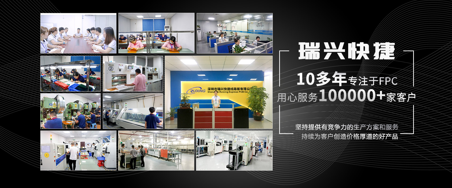
In the PCBA production process, it is necessary to rely on a lot of machinery and equipment to assemble a board. The quality level of a factory's machinery and equipment directly determines the manufacturing capability.
The basic equipment required for PCBA production includes solder paste printing machine, placement machine, reflow soldering, AOI detector, component shearing machine, wave soldering, tin furnace, washing machine, ICT test fixture, FCT test fixture, Aging test stands, etc., different scale PCBA processing plants, the equipment will be different.
-
 Hotline: 0755-27059800
Miss Guan: 13530507787 mailbox: szrxfpc@163.com address: Baoan District, Shenzhen, Sha Tin Street, and the 5 floor, E tower, Zhong Xi industrial park, affluent industrial area.
- Company introduction
- organizational
- development
- factories
- The enterprise culture
- Honorary certificate
About Us
- Single sided double sided FPC
- Soft line board FPC
- Door lock key FPC
- Medical hairdressing FPC
- Lamp lighting FPC
- Smart wear FPC
- FPCA chip board
- Soft and hard combination plate
Product
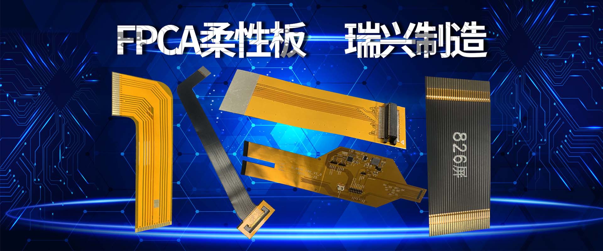
- FPC flexible plate
- Smart wear
- Fingerprint keys
- Medical equipment
- LED
Application
- Process ability
- Operation
- Copy board service
Technical
- Contact information
- Company position
- recruitment


