
SMT process-FPC process technology
PCB (Printed Circuit Board) is a printed circuit board, referred to as a rigid board. FPC (Flexible Printed Circuit) is a flexible circuit board, also known as a flexible circuit board or a flexible circuit board, referred to as a soft board. The miniaturization of electronic products is an inevitable development trend. A considerable number of consumer products are surface mounted. Due to the assembly space, their SMDs are mounted on FPC to complete the assembly of the whole machine. FPC is used in calculators, mobile phones, digital cameras. , digital video cameras and other digital products have been widely used, and the surface mount of SMD on FPC has become one of the development trends of SMT technology.
There are many differences in the process requirements of SMT on the surface of FPC and the SMT solution of traditional rigid PCB. To do a good job in the SMT process of FPC, the most important thing is positioning. Because the hardness of the FPC board is not enough and it is relatively soft, if the special carrier board is not used, the fixing and transmission cannot be completed, and the basic SMT processes such as printing, patching, and passing through the furnace cannot be completed. The following is a detailed description of the process points of FPC pretreatment, fixing, printing, patching, reflow soldering, testing, inspection, sub-board and other processes in FPC SMT production.
one. Preprocessing of FPC
The FPC board is relatively soft, and is generally not vacuum-packed when it leaves the factory. It is easy to absorb moisture in the air during transportation and storage. It needs to be pre-baked before SMT casting to slowly and forcibly discharge the moisture. Otherwise, under the high temperature impact of reflow soldering, the moisture absorbed by the FPC will quickly vaporize into water vapor and protrude the FPC, which may easily cause poor delamination and blistering of the FPC.
The pre-baking conditions are generally 80-100 °C for 4-8 hours. In special cases, the temperature can be increased to above 125 °C, but the baking time needs to be shortened accordingly. Before baking, be sure to do a small sample test to determine whether the FPC can withstand the set baking temperature, and you can also consult the FPC manufacturer for suitable baking conditions. When baking, the stack of FPC should not be too much. 10-20PNL is more suitable. Some FPC manufacturers will put a piece of paper between each PNL for isolation. It is necessary to confirm whether the paper used for isolation can withstand the set baking. temperature, if it is not possible to remove the isolation paper, and then bake. After baking, the FPC should have no obvious discoloration, deformation, warping, etc., and it can only be cast after passing the random inspection by IPQC.
two. Production of special carrier boards
According to the CAD file of the circuit board, the hole positioning data of the FPC is read to manufacture a high-precision FPC positioning template and a special carrier board, so that the diameter of the positioning pin on the positioning template is the same as that of the positioning hole on the carrier board and the hole diameter of the positioning hole on the FPC. match. Many FPCs are not of the same thickness because of the need to protect part of the circuit or for design reasons. Some places are thick and some places are thinner, and some have reinforced metal plates, so the joint between the carrier board and the FPC needs to be pressed according to the The actual situation is to process and grind the grooves, and the function is to ensure that the FPC is flat during printing and placement. The material of the carrier board is required to be light and thin, high strength, less heat absorption, fast heat dissipation, and small warpage deformation after multiple thermal shocks. Commonly used carrier materials include synthetic stone, aluminum plate, silica gel plate, special high temperature resistant magnetized steel plate, etc.
Ordinary carrier board: Ordinary carrier board is convenient in design and quick in proofing. Commonly used common carrier materials are engineering plastics (synthetic stone), aluminum plates, etc. The engineering plastic carrier has a lifespan of 3000-7000 times. It is easy to operate, has good stability, is not easy to absorb heat, and is not hot to the hand. The price is 5 times that of aluminum plates. above. The aluminum carrier plate absorbs heat quickly, there is no temperature difference inside and outside, the deformation can be easily repaired, the price is cheap, and the service life is long.
Silicone board: The material is self-adhesive, FPC is directly attached to it, no tape is needed, and it is easy to remove, no glue residue, and high temperature resistance. In the process of using the silicone plate, a chemical process is adopted. The silicone material will age and decrease in viscosity during use. The viscosity will also decrease when it is not cleaned during use.
Magnetic fixture; special high temperature resistant (350 ℃) steel sheet strengthens the magnetization performance treatment to ensure the "permanent magnet" during the reflow soldering process, with good elasticity, good flatness, and no deformation at high temperature. Because the steel sheet treated with enhanced magnetization has pressed and flattened the surface of the FPC, the FPC can be prevented from being badly welded by the reflow wind during reflow soldering, so as to ensure the stable welding quality and improve the yield. As long as it is not damaged by man-made and accidental damage, it can be used for a long time and has a long life. The magnetic fixture also protects the FPC from heat, and will not cause any damage to the FPC when the board is taken out. However, the design of the magnetic fixture is complex and the unit price is high, so it has a cost advantage in mass production.
three. production process.
Here we take the common carrier board as an example to describe the SMT points of FPC in detail. When using a silicone plate or a magnetic fixture, it is much more convenient to fix the FPC, and no tape is required. The process points of printing, patching, welding and other processes are: the same.
1. Fixing of FPC:
Before SMT, the FPC** needs to be fixed on the carrier first. In particular, it is important to note that the shorter the storage time between printing, placement and soldering after the FPC is fixed on the carrier, the better.
The carrier board is available with or without locating pins. The carrier board without locating pins needs to be used together with the locating template with locating pins. First, put the carrier board on the locating pins of the template, so that the locating pins are exposed through the locating holes on the carrier board. On the exposed positioning pins, use tape to fix it, and then separate the carrier board from the FPC positioning template for printing, patching and welding. Several spring positioning pins with a length of about 1.5mm have been fixed on the carrier board with positioning pins. The FPC can be directly sleeved on the spring positioning pins of the carrier board one by one, and then fixed with tape. In the printing process, the spring positioning pin can be completely pressed into the carrier plate by the steel mesh without affecting the printing effect.
Method 1 (single-sided tape fixation): Use thin high-temperature resistant single-sided tape to fix the four sides of the FPC on the carrier board, so as not to allow the FPC to be offset and warped. The viscosity of the tape should be moderate, and it must be easy to peel after reflow soldering. No glue residue on it. If you use an automatic tape machine, you can quickly cut tapes of the same length, which can significantly improve efficiency, save costs, and avoid waste.
Method 2 (fixed with double-sided tape): First stick the high temperature resistant double-sided tape on the carrier board, the effect is the same as that of the silicone board, and then paste the FPC to the carrier board, pay special attention to the viscosity of the tape not too high, otherwise it will peel off after reflow soldering It is easy to cause the FPC to tear. After repeatedly passing through the oven, the viscosity of the double-sided tape will gradually decrease. When the viscosity is too low to reliably fix the FPC, it must be replaced immediately.
This station is a key station to prevent the FPC from being dirty, and it is necessary to wear finger cots for operation. Before the carrier board is reused, it needs to be cleaned properly. It can be scrubbed with a non-woven fabric dipped in cleaning agent, or an anti-static sticky roller can be used to remove foreign objects such as surface dust and tin beads. Do not use too much force when picking and placing FPC. FPC is fragile and prone to creases and breaks.
2. Solder paste printing of FPC:
FPC has no special requirements for the composition of solder paste. The size and metal content of solder ball particles are subject to whether there is a fine-pitch IC on the FPC. However, FPC has higher requirements on the printing performance of solder paste, and the solder paste should have excellent Thixotropy, the solder paste should be able to be easily printed and demolded and firmly attached to the FPC surface, without poor demolding, blocking stencil leaks, or collapsing after printing.
Because the FPC is loaded on the carrier board, and there is a high temperature resistant tape for positioning on the FPC, so that the plane is inconsistent, so the printing surface of the FPC cannot be as flat as the PCB and has the same thickness and hardness, so it is not suitable to use a metal scraper, but a hardness of 80. -90 degree polyurethane type scraper.
The solder paste printer preferably has an optical positioning system, otherwise it will have a great impact on the printing quality. Although the FPC is fixed on the carrier board, there will always be some tiny gaps between the FPC and the carrier board, which is different from the PCB rigidity. Therefore, the setting of equipment parameters will also have a greater impact on the printing effect.
The printing station is also a key station to prevent FPC from being dirty. It is necessary to wear finger cots for operation. At the same time, it is necessary to keep the station clean and clean the steel mesh frequently to prevent the solder paste from contaminating the gold fingers and gold-plated buttons of the FPC.
3. FPC patch:
According to the characteristics of the product, the number of components and the placement efficiency, it can be placed by a medium-speed placement machine or a high-speed placement machine. Since there is an optical MARK mark for positioning on each piece of FPC, there is little difference between SMD mounting on the FPC and mounting on the PCB. It should be noted that although the FPC is fixed on the carrier board, its surface cannot be as flat as the PCB hard board. There will definitely be a partial gap between the FPC and the carrier board. Therefore, the nozzle drop height, blowing pressure, etc. Need to be set, the nozzle moving speed needs to be reduced. At the same time, the majority of FPC is connected to the board, and the yield of FPC is relatively low, so it is normal for the entire PNL to contain some poor PCS, which requires the placement machine to have the BAD MARK identification function, otherwise, in the production of such non- When the entire PNL is a good board, the production efficiency will be greatly reduced.
4. Reflow soldering of FPC:
A forced hot air convection infrared reflow oven should be used, so that the temperature on the FPC can change more evenly and reduce the occurrence of poor soldering. If single-sided tape is used, because only the four sides of the FPC can be fixed, the middle part is deformed in the hot air state, the pad is easily inclined, and the molten tin (liquid tin at high temperature) will flow, resulting in empty welding, continuous welding, The tin bead makes the process failure rate higher.
1) Temperature curve test method:
Due to the different heat absorption of the carrier board and the different types of components on the FPC, the temperature rises at different speeds after being heated during the reflow soldering process, and the absorbed heat is also different. Therefore, the temperature curve of the reflow soldering furnace is carefully set, and the quality of the soldering is affected. Great influence. A more secure method is to place two FPC-equipped carrier boards on the front and back of the test board according to the actual production carrier board spacing, and attach components to the FPC of the test carrier board, and use high-temperature solder wire to test the temperature. The probe is soldered to the test point, and the probe wire is fixed to the carrier board with high temperature tape. Note that the high temperature tape does not cover the test points. The test points should be selected near the solder joints and QFP pins on all sides of the carrier board, so that the test results can better reflect the real situation.
2) Setting of temperature curve:
In the furnace temperature debugging, because the temperature uniformity of the FPC is not good, it is best to use the temperature curve method of heating/holding/reflow, so that the parameters of each temperature zone are easier to control, and the FPC and components are affected by thermal shock. Some. According to experience, it is best to adjust the furnace temperature to the lower limit of the technical requirements of the solder paste. The wind speed of the reflow furnace is generally the lowest wind speed that the furnace can use. The stability of the reflow furnace chain is better, and there should be no jitter.
5. Inspection, testing and sub-board of FPC:
Since the carrier plate absorbs heat in the furnace, especially the aluminum carrier plate, the temperature is high when it comes out of the furnace, so it is best to add a forced cooling fan at the furnace outlet to help cool down quickly. At the same time, the operator needs to wear heat insulation gloves to avoid being attacked by the high temperature carrier plate. When taking the soldered FPC from the carrier board, the force should be even, and brute force should not be used to prevent the FPC from being torn or creased.
The removed FPC is visually inspected under a SMT magnifying glass of more than 5 times, focusing on inspection of surface glue residue, discoloration, gold finger tinning, tin beads, and IC pin air soldering and soldering. Since the surface of FPC cannot be very flat, the false positive rate of AOI is very high, so FPC is generally not suitable for AOI inspection, but with the help of special test fixtures, FPC can complete the test of ICT and FCT.
Since most FPCs are combined with boards, it may be necessary to do board separation before testing ICT and FCT. Although tools such as blades and scissors can also be used to complete board separation, the work efficiency and quality of work are low, and the scrap rate is high. If it is the mass production of special-shaped FPC, it is recommended to make a special FPC stamping parting die for stamping and dividing, which can greatly improve the work efficiency. Solder cracks can be effectively avoided.
Four. summary
For SMD placement on the FPC, the precise positioning and fixing of the FPC is the key point. The key to the quality of the fixing is to make a suitable carrier board. This is followed by pre-baking, printing, placement and reflow of FPC. Obviously, the SMT process of FPC is much more difficult than that of PCB rigid boards, so it is necessary to set the process parameters accurately. At the same time, strict production process management is also important. It is necessary to ensure that operators strictly implement every stipulation on the SOP, and follow the instructions of the SOP. Line engineers and IPQC should strengthen inspections, find out the abnormal situation of the production line in time, analyze the reasons and take necessary measures, in order to control the poor rate of FPC SMT production line within dozens of PPM.
-
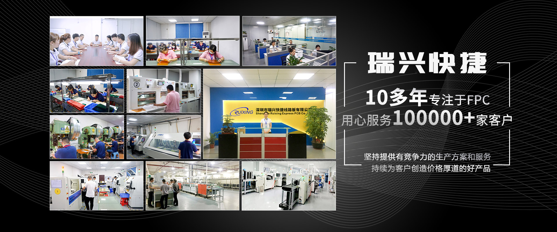
 Hotline: 0755-27059800
Miss Guan: 13530507787 mailbox: szrxfpc@163.com address: Baoan District, Shenzhen, Sha Tin Street, and the 5 floor, E tower, Zhong Xi industrial park, affluent industrial area.
- Company introduction
- organizational
- development
- factories
- The enterprise culture
- Honorary certificate
About Us
- Single sided double sided FPC
- Soft line board FPC
- Door lock key FPC
- Medical hairdressing FPC
- Lamp lighting FPC
- Smart wear FPC
- FPCA chip board
- Soft and hard combination plate
Product
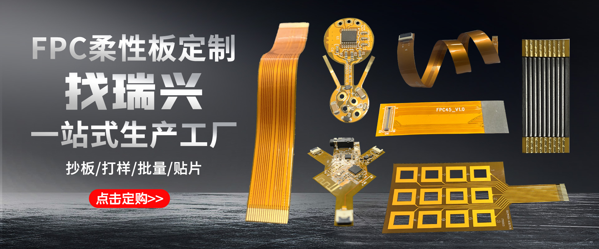
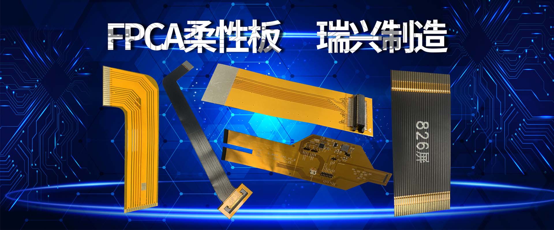
- FPC flexible plate
- Smart wear
- Fingerprint keys
- Medical equipment
- LED
Application
- Process ability
- Operation
- Copy board service
Technical
- Contact information
- Company position
- recruitment


